SAVE THE DATE! The Tin Can Sailors 2024 National Reunion Will Be Held In Exciting, Historic New Orleans From Sept. 8th-12th. More Information Coming Soon, Check Our Facebook Page For Future Announcements.
Home » Ships » Ordnance Photos and Articles
Our newsletter has often included features on destroyer weapons systems. Here are some from past editions.
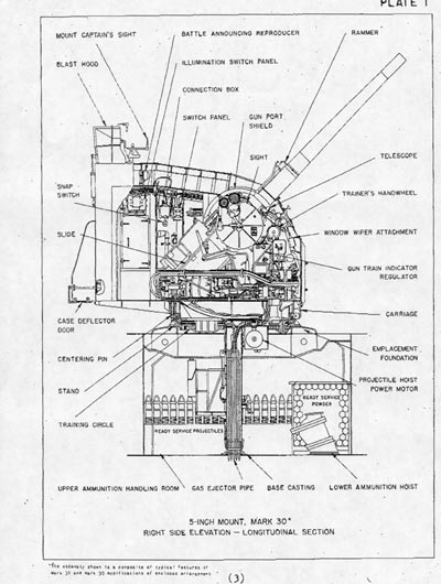
5″/38 Twin Mount5″/54 Single Mount20-mm Single and Twin Mounts3″/50 Single and Twin MountsThe Mark 10/11 “Hedgehog” Projector
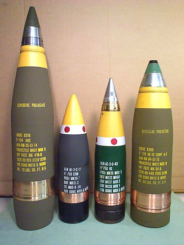
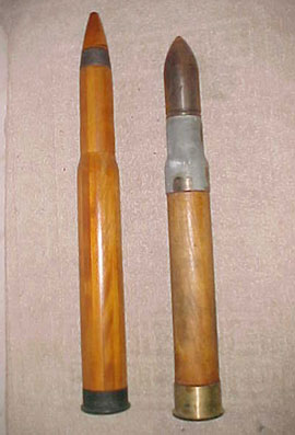
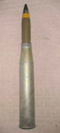
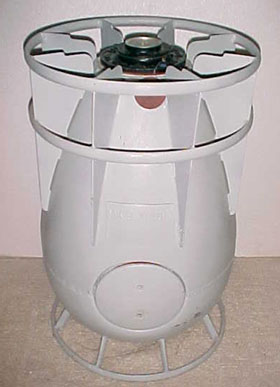
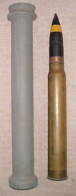
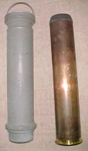
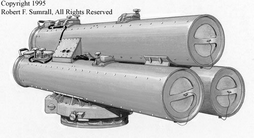
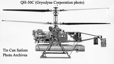
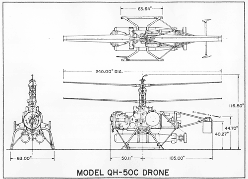
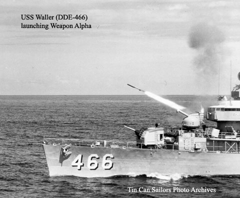
Anti-Submarine Rocket (ASROC)The 21-in Quintuple MK 14 and MK 15 Torpedo TubesGun AmmunitionWeapon A (Mark 108)